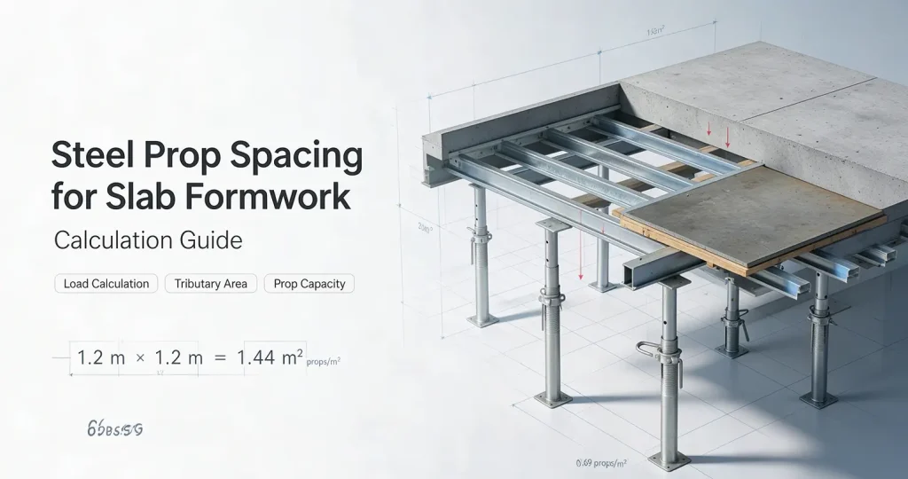
Steel prop spacing for slab formwork must be calculated from the construction-stage load and the prop’s verified capacity at its actual extension. On a trial 1.2 m × 1.2 m grid, an interior prop supports 1.44 m². At a service load of 7.50 kN/m², the resulting axial load is 10.80 kN. It is not a universal site rule. This is only a preliminary check. The formwork, bearers, bracing, connections, prop bases and supporting floors must also be verified before the grid becomes an erection layout.
What Is Steel Prop Spacing?
It is the centre-to-centre distance between props in both plan directions. For a 1.2 m × 1.2 m grid:
Tributary area = 1.2 × 1.2 = 1.44 m²
Theoretical density = 1 ÷ 1.44 = 0.69 props/m²
This density helps with early budgeting, but it is not the order quantity. Real layouts need additional positions along edges, beams and openings.
People searching for steel props spacing for slab often expect one standard distance. There is none: the answer changes with the slab, formwork system, prop model, extension and support conditions.
Factors Affecting Spacing

The temporary-works designer must follow the complete load path:
- Slab thickness and concrete unit weight
- Formwork weight and construction activity
- Sheathing, joist and bearer spans
- Prop capacity at the installed height
- Eccentricity, plumbness and bracing
- Base and sole-board bearing
- Beams, drops, openings, edges and reshoring
A prop can perform well in a compression test while the installed system remains unsafe. A bearer may deflect, a base may settle, or an unbraced row may move during the pour.
For US projects, OSHA 29 CFR 1926.703 requires formwork to support all reasonably anticipated vertical and lateral loads without failure.
Slab Thickness and Concrete Load
A slab formwork prop calculation starts with:
Concrete load = slab thickness × concrete unit weight
The table below uses 25 kN/m³ as the calculation value for this example. Confirm the actual unit weight specified for the project. If the selected value already includes the reinforcement allowance, do not add the reinforcement weight again.
| Slab thickness | Concrete load at 25 kN/m³ |
|---|---|
| 120 mm | 3.00 kN/m² |
| 150 mm | 3.75 kN/m² |
| 180 mm | 4.50 kN/m² |
| 200 mm | 5.00 kN/m² |
| 250 mm | 6.25 kN/m² |
Fresh concrete is only part of the construction-stage load. Add the actual formwork weight, applicable construction load and any local loads from equipment or stored materials.
Prop Capacity at Different Extensions
A telescopic prop generally becomes more sensitive to buckling as it extends. Never assume that its capacity at minimum height also applies at maximum height.
Our SGS Failure Test Results
Our SGS test report covers a Q235B prop specified as 2.0–3.5 m. Under the client-defined axial failure-load test method, SGS recorded:
| Test height | Failure load | Failure mode |
|---|---|---|
| 2,000 mm | 91.50 kN | Pin deformed |
| 3,500 mm | 30.47 kN | Pin deformed |
The recorded failure load fell by approximately 66.7% between the two test heights. This is useful evidence of why buyers should compare products at the required extension rather than relying on a headline maximum load.
The percentage is specific to the tested prop and test conditions and should not be generalized to other prop models.
These figures are specimen failure loads. They are not a safe working load, permissible working load or design resistance. They cannot be converted into a site rating by applying an arbitrary safety factor.
Our Steel Prop Product Range
Our product range includes:
| Item | Available options |
|---|---|
| Steel material | Q235B and Q355B |
| Tube diameter | 40, 48, 56, 60, 76 and 89 mm |
| Wall thickness | 1.6, 1.8, 2.0, 2.2 and 2.4 mm |
| Duty | Light, medium and heavy |
| Finish | Painted, powder-coated, electro-galvanized, pre-galvanized and hot-dip galvanized |
These are product options, not a universal capacity table. Buyers should match the exact tube sizes, steel grade, pin, weld details and extension to verified load data.
Contact us for the full load-capacity table matched to your exact working height and project requirements.
Why Adjustable Steel Prop Spacing Changes With Height
If verified capacity decreases at greater extension, the designer may close the grid, choose a stronger prop or use a framed shoring system. The choice should be based on capacity data for the exact configuration.
Calculation Example
Assume an 180 mm slab with:
- Concrete: 0.18 × 25 = 4.50 kN/m²
- Formwork: 0.50 kN/m²
- Construction allowance: 2.50 kN/m²
Total service load = 4.50 + 0.50 + 2.50 = 7.50 kN/m²
The last two figures are assumptions for this example. They are not universal code values or BYTHAI product data.
For a trial 1.2 m × 1.2 m grid:
Load per interior prop = 7.50 × 1.44 = 10.80 kN
Now assume that the selected prop has a verified permissible working load of 20 kN at the installed height, using the same service-load basis.
This 20 kN is an illustrative design value for calculation only. Actual permissible working loads must be taken from our certified load table and applied in accordance with the project’s required safety factors and design method.
Utilization = 10.80 ÷ 20 = 54%
The axial check passes under these assumptions; the complete layout does not automatically pass. The sheathing, joists, bearers, connections, bracing, bases and supporting floor still need to be checked.
The calculation method must also remain consistent. Compare service loads with permissible working loads, or factored loads with design resistance. Do not mix the two methods.
How Many Steel Props per Square Meter?
For a regular grid, use:
Props/m² = 1 ÷ (spacing A × spacing B)
| Trial grid | Theoretical density |
|---|---|
| 1.0 × 1.0 m | 1.00 prop/m² |
| 1.2 × 1.2 m | 0.69 prop/m² |
| 1.5 × 1.5 m | 0.44 prop/m² |
These figures are suitable for early estimating, not final ordering. For purchasing, count the positions on the approved drawing and include edge supports, beam lines, openings and specified spares.
Installation Layout
Set Out, Brace and Inspect
Mark separate support zones around beams, columns, drop panels, openings and slab edges. Keep every prop plumb, seat its head centrally beneath the bearer and support the full base plate on a sound surface or designed sole board.
Do not use bricks, loose timber or unapproved packing to gain height.
Individual props do not form a stable shoring system by themselves. Install the specified horizontal and diagonal restraint. Before the pour, inspect the tubes, pins, adjustment nuts, welds, heads, plates and connections. Repeat the checks while concrete is being placed.
For full site management standards, see the UK HSE temporary works guidance.
Common Mistakes
- Treating the 91.50 kN failure result as a working load
- Using one grid for the main slab, beams, edges and maximum-height props
- Checking the props but ignoring plywood, bearers, bases or the supporting floor
- Ordering by slab area alone and missing boundary supports
- Mixing similar-looking rental stock without checking identification and capacity
- Removing or loosening supports before the specified concrete strength is reached
For adjustable telescopic steel prop specifications, refer to BS EN 1065.
For concrete formwork planning, design and construction guidance, refer to ACI 347R, Guide to Formwork for Concrete.

FAQ
What Is a Safe Steel Prop Spacing for Slab Formwork?
There is no universal safe distance. A trial grid can be assessed during estimating, but the approved layout must reflect the actual loads, prop capacity at extension, bearer system, bracing and supporting structure.
Is Acrow Prop Spacing Different?
“Acrow prop” is often used as a generic name for an adjustable telescopic prop. Products still differ in tube dimensions, pin details and capacity, so acrow prop spacing must follow the actual manufacturer’s data.
Does a Thicker Slab Need More Props?
A thicker slab increases the concrete load per square metre, but adding props is not the only possible response. The designer may instead change the joists, bearers, prop type or complete shoring system.
Can the SGS Values Be Used as the SWL?
No. They are failure loads from two specimens tested under a client-defined method. Use permissible working load or design-resistance data verified for the exact product and accepted for the project.
What Should Buyers Request From a Supplier?
Ask for the exact model, steel grade, inner and outer tube dimensions, wall thickness, closed and extended lengths, capacity at the required extensions, test or design basis, applicable standard, finish and batch traceability.
The supplied documents should match the products delivered to the project or rental fleet.
Conclusion
Choosing steel prop spacing starts with the construction-stage area load and ends with a check of the entire support system. Our SGS results show why extension matters: the tested failure load was 91.50 kN at 2,000 mm and 30.47 kN at 3,500 mm.
Contractors, buyers, rental companies and QA/QC inspectors should compare products at the required project height and work from an engineered layout rather than a catalogue maximum.
Need props for your slab formwork project? Request a custom steel prop quotation with your required working height, slab thickness, quantity and applicable project standard.